About
This is a guide on how to set up and operate the new M4 datalogger, accompanying plotter script, and experimental GUI app for the 2025 MD Anderson trip.
Setting Up Your Computer and M4!
Please Read!
This guide should apply to everyone on a modern operating system (Windows, MacOS, most modern Linux distros).
Also, if I refer to a script, I am most likely referring to a Python program that will run on your computer/laptop. If I refer to a sketch, I am most likely referring to an Arduino program that will run on your MCU.
Tip
Since I primarily use Linux, I will refer to Terminal, cmd, PowerShell, and whatever other analogous app as “terminal”. For Windows users, if you see a command run as
sudoin the guide below, you will have to run that same command (without includingsudo) in an elevated/administrator cmd or PowerShell window.
uv is not recognized?
Sometimes, trying to run any
uvcommands in terminal will throw an error saying it’s an unrecognized command.If you just installed
uv, try closing the open terminal window and reopening. If it still doesn’t work, you may have installeduvincorrectly.
Arduino IDE says my device is unrecognized!
Sometimes, our sketches “lock” the board in a way that’s not always recoverable from our computer. A simple fix is to rapidly double click the little black reset button on your MCU. This will switch the MCU into bootloader mode, which conveniently halts the currently running sketch until a new one is uploaded.
Make sure to reselect your MCU port! You can now try uploading your sketch again.
Arduino IDE hangs forever or fails after a while when I'm uploading a sketch!
See “Arduino IDE says my device is unrecognized!”
General Requirements
- Arduino IDE 2.3+
- Legacy IDE (1.8.X) should work, but the GUI is different and you will have to find the analogous menus.
- uv
- Using
uv python install, install a recent version of Python (3.12+) - Please double check uv’s recognized Python installations by running
uv python listin terminal!
- Using
- A Local Copy of our Code
- Here is a link to the zip.
- If you use this link, make sure you extract the contents somewhere memorable before moving on.
- Here is a link to the zip.
- A Local Copy of the GUI
- Make sure to pull the
textual-attemptbranch
- Make sure to pull the
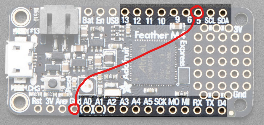
- Install a Toggle Switch connecting
GPIO 5andGndpins:
Arduino IDE
Boards Manager
The bare IDE will not recognize our microcontrollers (MCUs) without some set up.
- Open Arduino IDE.
- Go to File→Preferences
- At the bottom, there will be an empty text box titled “Additional boards manager URLS”. Paste in the following:
https://adafruit.github.io/arduino-board-index/package_adafruit_index.json
- …and click OK.
- Next, in the left sidebar, open the Boards Manager.
- Search for and install Adafruit SAMD Boards.
- This will install the proper dependencies for our MCUs.
Library Manager
The following libraries are required for the datalogger and the data-offloading
- SdFat - Adafruit Fork
- and associated dependencies (should auto install)
- TinyUSB
Validating Your Setup!
Now we’ll run a test program on your MCU to make sure the basics are set up properly. Make sure your MCU is plugged into your computer before proceeding.
- In Arduino IDE, go to File→Examples→Basics→Blink. This should look something like this:
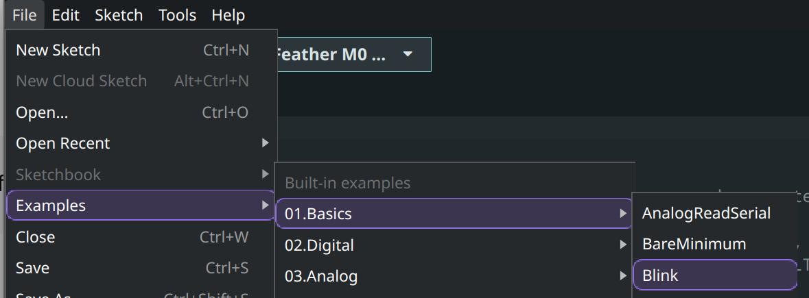
- This will open a new window with the Blink example sketch.
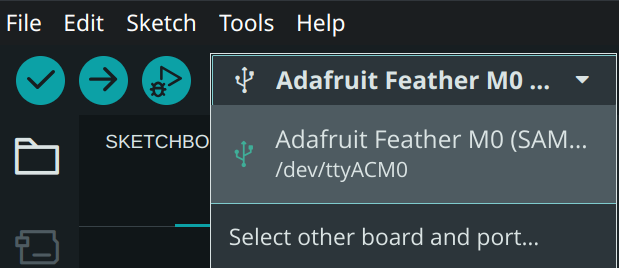
- In Arduino IDE, you should see a dropdown menu in the top left that looks something like this:
- Windows users will see ports such as
COM6orCOM4 - Mac users will see ports such as
/dev/cu.usbmodem1101- You may see a pop up to install xcrun. Allow the install to finish before proceeding.
- Linux users will see ports such as
/dev/ttyACM0
- If your setup is correct, you should see an entry in there for every connected MCU. Select the one you’d like to test.
- Click the → button in the top left to compile and upload the example sketch onto your MCU!
- Once the upload is complete, you should see a small LED on your MCU start blinking near the USB port. If everything so far has worked, then you should be good to go!

Using the MDA Sketch!
Dependencies
The Code
Please make sure you are looking at the cleanup branch!
- You will find the sketch at:
IRIS-Project\packages\M4\Toggle Switch Datalogger\dma_dual_adc_unified_SfFat\dma_dual_adc_unified_SfFat.ino.- You need all files in here. Not just
dma_dual_adc_unified_SdFat.ino
- You need all files in here. Not just
Hardware
- MCU: Adafruit Feather M4 Express with SD+RTC Featherwing
- SD Card formatted to exFat
- Toggle Switch connecting
GPIO 5andGndpins - Data Collection pins:
- A4
- A1
- A2
- A3
Running the Sketch
- Open
dma_dual_adc_unified_SfFat.inousing Arduino IDE, or open Arduino IDE first and go to File→Open… to opendma_dual_adc_unified_SfFat.ino.- You may see a new IDE window open with the sketch opened.
- Use the dropdown menu to select your M4 MCU:
- Make note of the listed port!
- In this case, the MCU is connected to serial port
/dev/ttyACM0
- In this case, the MCU is connected to serial port
- Click the → button in the top left to compile and upload the sketch. Wait for it to complete.
- The MCU should now be ready to collect data.
Important
The M4 will collect data when the switch is in the OFF position. The M4 will pause data collection when the switch is in the ON position.
This is a bug, but has no other affects besides inverting switch behavior.
Halt data collection before cutting power or removing SD card!
In order to reduce performance impacts, the MCU only safely commits recent data to the SD card when the switch is flicked to the ON position (AKA data collection is paused).
Using the Dat Plotter Script!
Dependencies
The Code
Please make sure you are looking at the cleanup branch of the IRIS-Project repo!
- The script can be found at:
IRIS-Project\packages\M4\Toggle Switch Datalogger\m4_dma_dat_plotter\m4_dma_dat_plotter.py. - You will find the sketch at:
IRIS-Project\packages\M4\Toggle Switch Datalogger\dma_dual_adc_unified_SfFat\dma_dual_adc_unified_SdFat.ino.- You need all files in here. Not just
dma_dual_adc_unified_SdFat.ino
- You need all files in here. Not just
Python
uvwill handle all dependencies via thepyproject.tomlfile when you run the script.
Running the Script!
- Open a terminal window in the script’s directory, or
cdinto it as needed. - Run the script via
uv run ./m4_dma_dat_plotter.py [-seq] <NUM_RESULTS> <DATA DIRECTORY>NUM_RESULTS: same value as found inconfig.h. Currently, 8192.DATA DIRECTORY: the directory path which holds the desired.datfiles to plot